
 ไทย
ไทย
+86-17757929999
Product Search
Correct sizing of an industrial heating system directly affects efficiency, operating cost, and equipment lifespan. A properly designed Thermal Fluid Heater ensures stable process temperature control while avoiding oversizing or underperformance issues that increase fuel consumption and maintenance frequency. Industrial users often compare an Oil Thermal Fluid Heater with a Gas Thermal Fluid Heater depending on available fuel sources, heat demand, and plant layout requirements.
Heat load calculation is the foundation of sizing.
Key inputs include:
Typical reference values:
A miscalculation at this stage often results in unstable outlet temperature or excessive fuel consumption.
Thermal oil characteristics define system limits.
Common design parameters:
A stable fluid selection improves heater life and reduces oxidation risk under continuous high-temperature operation.
Different industries prefer different combustion systems.
Both systems share similar heat transfer principles but differ in burner design and fuel handling systems.
Proper circulation ensures uniform heating across the system.
Typical engineering values:
Insufficient flow causes overheating on coil surfaces, which reduces thermal oil lifespan and increases coking risk.
Heat transfer performance depends on coil geometry.
Engineering considerations:
Our company uses optimized serpentine coil structures to improve heat distribution and minimize localized overheating.
Thermal oil expands significantly at high temperature.
Standard configuration includes:
A properly sized expansion system prevents overpressure and oil degradation.
Burner capacity must match peak thermal demand, not average load.
Reference guideline:
Example:
Thermal loss reduction is often overlooked.
Recommended technical specifications:
Proper insulation can reduce energy loss by up to 15–25%.
Modern thermal systems rely heavily on automation.
Key features include:
Automation improves long-term operational stability and reduces operator error.
Experienced designers always include safety buffers:
This prevents system underperformance during seasonal or production changes.
Industrial users often choose thermal fluid heaters for:
A correctly sized system ensures stable continuous operation under varying production loads.
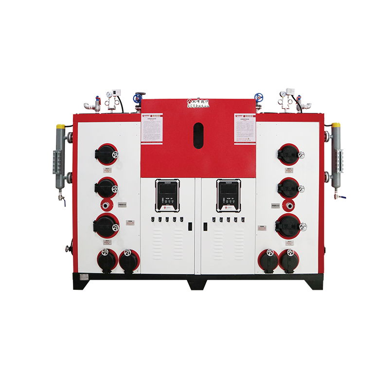
Product Introduction and FeatureThe SFeng LHG-s series biomass coal fired steam generator is a semi-...
See Details
Product Introduction and FeatureThe SFeng DZG Series solid fuel biomass/coal fired steam boiler has ...
See Details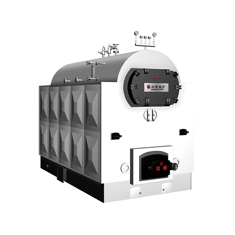
Product Introduction and FeatureDZG structure coal-fired steam boiler features a compact and single-...
See Details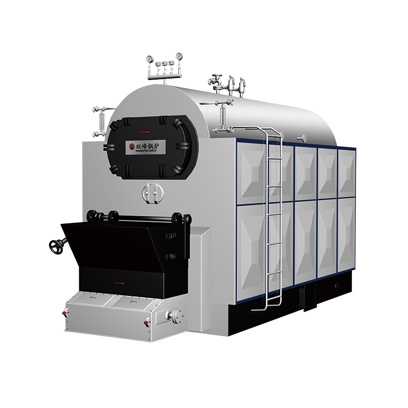
Product Introduction and FeatureThe DZL-S energy-saving and environmentally friendly steam boiler is...
See Details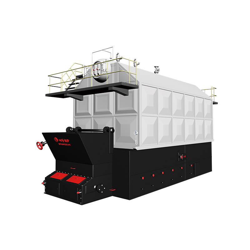
Product Introduction and FeatureSZI-S type energy-saving and environmentally friendly steam boiler i...
See Details
+86-17757929999

.png)
No. 150 Zhenxing Road, Jinhua, Zhejiang, China

With seven decades of expertise in energy-efficient and eco-friendly thermal equipment including steam boilers, steam generators, and pressure vessels, we operate as a nationally recognized high-tech enterprise offering integrated solutions from R&D and design to manufacturing, installation, maintenance, retrofitting, and after-sales service.
Copyright Zhejiang Shuangfeng Boiler Manufacturing Co., Ltd. All Rights Reserved.
![]()
Wuyi Generator Factory